Quick links:
Famous tasks:
Photographs of operant chamber hardware (2000)
A) Computer and Amplicon digital I/O hardware
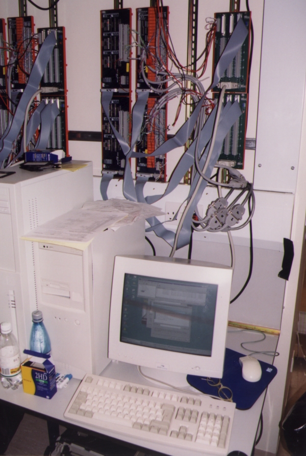
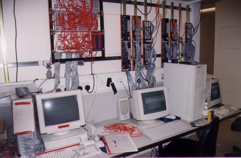
1. A single system controlling 6 operant chambers.
At the bottom of the photo is the controlling PC, with a few bottles of contraband water nearby and other debris belonging to the researcher using this equipment. This PC has two cards in the back of it, which are connected by the two thick grey cables to the wiring panels in the right-hand column of the rack above the computer. These racks are made by Amplicon. These would be sufficient if the devices being controlled used TTL voltage (5V), but as they are 28V devices additional boards are required; therefore the wiring panels are connected by ribbon cables to optoisolated input boards (left column) and relay output boards (centre column; the relays are orange). The right-hand wiring panels also serve as a distribution board for the power cables (red and black wires).
More grey cables emerge from the bottom-right corner of the equipment rack; these wires come directly from the operant chambers in a different room, and are connected via 25-way connectors into further pieces of grey 25-way cable that are run to the input and output boards.
Though the screen is hard to make out, the computer is running a number of second-order schedules of IV cocaine reinforcement. This was the first computer to run Whisker.
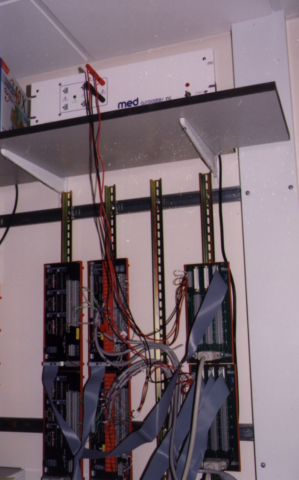
2. A similar but higher view showing the 28V power supply that drives the relay control board and the operant chambers themselves. The I/O boards clip onto vertical strips of DIN rail, which is extremely cheap stuff. (Something nasty seems to have happened to the film in this photo.)
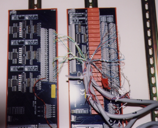
3. A close-up of an input panel (left) and an output panel (right).
The operant chambers being used are from Med Associates; their input devices (such as levers and infrared detectors) short their data lines to ground when activated, and their output devices (lights, lever motors, infusion pumps, etc.) are activated by connecting their data line to ground.
Whisker imposes no limitations on the way your system is wired. This particular system is wired to use one input panel and one output panel to control three boxes; the three grey cables each contain all the wires running to a single operant chamber.
The INPUT panel provides optoisolated inputs, and LEDs indicate the current state of the input lines at all times.
The OUTPUT panels are relay-based (the relays are orange). You have access to all relay pins when wiring your devices.
If you look carefully, you will be able to see the paperclips cunningly placed to connect, for example, all the relay COM(mon) pins together. This saves bits of wire, although I'm the first to admit that it's not pretty.
4. Two Whisker systems (right-hand side), together with an Acorn Archimedes (left) running Arachnid from Cenes Cognition, previously Paul Fray Ltd, and now Cambridge Cognition. Arachnid was previously the main operant control system used in our lab. Whisker is supplanting it. It has to be admitted that the wiring panels used on the Archimedes are easier to wire, though much more expensive than the Amplicon kit. The left-hand of the two PCs visible has an overly-large case.
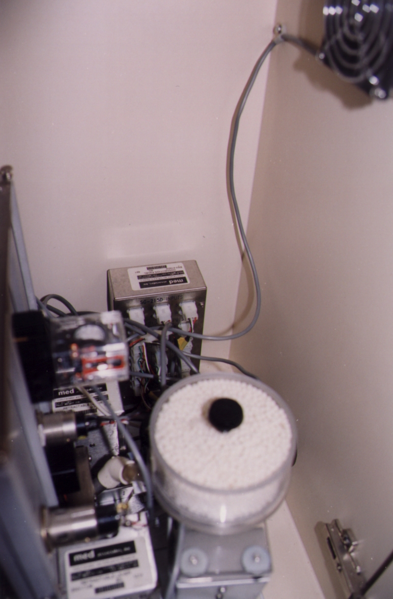
B) Inside an operant chamber
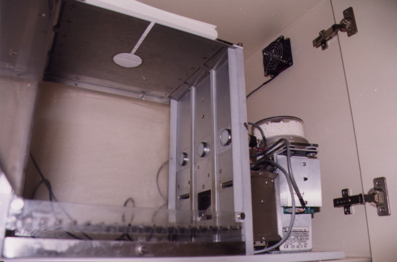
1. The interior of a rat operant chamber. (This is not a chamber rigged for IV work.) A pellet dispenser is visible on the right; on the main wall of the chamber there are three stimulus lights, two retractable levers, and an alcove where the pellets arrive. The alcove is also fitted with a liquid dipper, a small light, and an infrared nosepoke detector. There is a houselight in the top left corner of the box (not visible) and a clicker relay mounted on the wall above the alcove. The floor is a steel grid with a waste collecting tray beneath. I took this photo from a low angle not just to give you a rats'-eye view but because I hadn't cleaned the floor recently. The ceiling has a hole in because this was an IV self-administration chamber before I got to it; the book on top of the ceiling prevents rats from jumping out of the hole. (I was extremely impressed when I first witnessed a rat doing this, but it then proceeded to ignore all the food available and ate the wiring.) The whole apparatus is inside a sound-attenuating chamber.
2. The wiring panel at the back of the operant chamber. Devices are plugged into the steel box, which has a 25-way D connector on it. A 25-way cable connects this directly to the controlling digital I/O hardware pictured above.